Debye Circuit
The Debye circuit is a common model used for determining ionic conductivity in polymer electrolytes. However, it can occasionally cause confusion and misinterpretation of results as the visibility of some processes in the impedance spectrum can depend on the material properties and experimental conditions. We’ll take a look at why this might be on this page.
The Debye circuit is often used to interpret the impedance spectra of polymer electrolyte films sandwiched between blocking electrodes (i.e., electrodes that don’t undergo any reaction themselves), such as steel, or gold. This is a common method for calculating ionic conductivity of these materials. The circuit looks like this:
where Ri is the ionic resistance, Cdl is the double layer capacitance (represented by a constant phase element), and Cd is the dielectric capacitance.
It is important to account for the dielectric capacitance when making these measurements, because of the small inter-electrode distance (giving a higher dielectric capacitance) and a much higher ionic resistance of a polymer electrolyte than a liquid electrolyte (often 3 orders of magnitude higher, or more).
You should now start to see how the relaxation frequency associated with the semicircle that arises from the parallel Ri-Cd combination might well appear in the high frequency (1 kHz – 1 MHz) part of an impedance measurement, where it would normally be well outside the measurable range if the electrolyte was a more conductive liquid. Failure to account for this can lead the experimentalist to mistakenly assign the ionic resistance to the highest-frequency intercept of the real axis and the lower frequency resistance to some unknown charge transfer resistance (it does happen, I’m afraid).
Visualisation
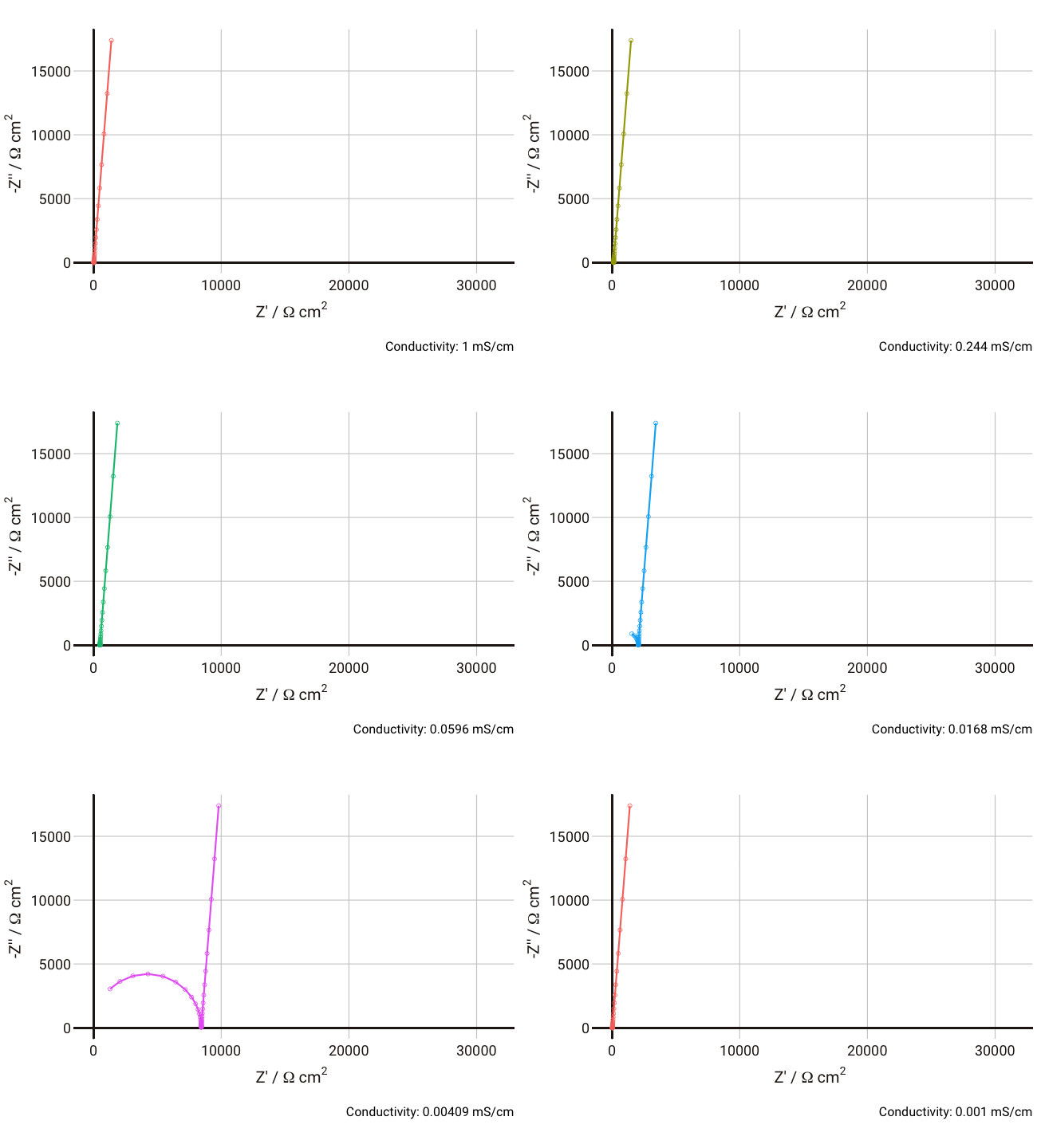
We can simulate the response of the Debye circuit for a typical polymer electrolyte between two blocking electrodes. Instead of directly using R and C values, we can calculate them from typical values of thickness, conductivity, and dielectric constant. If we say for example that we have a thickness
As the conductivity decreases, the resistance R increases, increasing the time constant R-Cd. It can be seen that that until the conductivity is below 0.02 mS cm-1, the semicircle associated with R-Cd is hardly visible as the relaxation frequency is well outside the measurement range. This hopefully shows more clearly why this phenomenon is rarely spotted away from measurements on poorly conductive samples. Under these conditions, the value of the capacitor Cd is ~4.4 × 10⁻¹¹ F cm-1, which is over five orders of magnitude lower than the double layer capacitance and thus easily distinguished in an equivalent circuit fitting.
Some typical conductivities of different materials as a guide: polymer electrolyte: 10-6 S cm-1; Li-ion battery electrolyte: 4 x 10⁻³ S cm-1; aqueous electrolyte: 10-1 S cm-1.

