Three- and four-electrode measurements
This content has been transferred from lacey.se and is not updated for this site yet.
In a previous page we looked at the Debye circuit as a model in polymer electrolyte characterisation. Keeping the cell components and cell design simple is a good strategy for getting simple, easily-to-analyse data. But what if you want to measure the impedance response of a complicated real system? Something like, a Li-ion battery, maybe, which has two electrodes essentially made of mixtures of electrochemically active powders?
In this case maybe the system is too complicated to be able to understand every process going on, especially when the electrochemical reactions are probably distributed very unevenly throughout the electrodes. But perhaps you just want to separate out the impedance of the positive electrode from the impedance of the negative electrode? This is useful in battery testing, because to be able to see the contributions of each electrode separately will give the tester some insight into, for example, whether one electrode is degrading faster than the other over long-term testing.
In principle, it is quite simple to do this by using a reference electrode, although practically designing and building a reliable cell might be more tricky. Here, I’ll share with you a demonstration experiment I did for some visiting students, as an example of separating out the contributions of the two electrodes in a small Li-ion test battery (since it worked almost perfectly on the first and only attempt!).
Essentially, I built a cell that looked like this on the inside:

It has a working electrode (positive electrode), which is a film of the battery active material mixed with carbon and a binder, and coated onto Al foil; a counter-electrode (negative electrode), which for simplicity in this case is just lithium metal foil; and two reference electrodes. Both reference electrodes are also made of lithium metal foil but cut into rings, which sit concentrically around the positive and negative electrodes – using references of this shape and placement means that the cell is as symmetric as possible, and gives as reliable impedance spectra as possible.
If you only want to measure the contribution from the positive and negative electrodes individually, you only need the one reference electrode. You’ll see why I’ve used two later on. There are also, of course, separators between the electrodes to prevent them from contacting each other inside the cell.
Why reference electrodes

If you’re a regular potentiostat user, you’ve probably noticed that it has four (or maybe more) leads with which you can connect up your electrochemical cells. Battery testing instruments too, usually have four leads, but usually connected up into pairs.
This is because the measurement of voltage and the transmission of current are divided between separate pairs of leads (also known as force and sense respectively). The current flows through the force leads, and the voltage is measured between the two sense leads. For battery testing (and usage), the force and sense leads for each electrode are simply connected to each other. This is a two-electrode measurement. If you separate the voltage measurement from one or both of the current-carrying electrodes, however, and measure the voltage between two different points (see the diagram on the right) – you can remove the contribution from those electrodes. This is the basis of the four-point probe.
If you are an electrochemist, you are probably familiar with the use of reference electrodes already. In that case, the aim is to place a stable voltage-sensing electrode as close as possible to the working electrode (to which the other sensing electrode is connected). The current flows through the counter electrode and the working electrode, but the potential drop across the cell is only measured between the working electrode and the reference electrode – the impedance associated with the counter electrode is not measured.
How does this work in practice?
Ok, let’s go back to the battery I made. I’ve drawn a simplified(!) equivalent circuit for the cell, and indicated where the reference electrodes are placed in relation to these different components.

Between the WE (positive) electrode and RE1 is the impedance of my battery electrode (with a reasonable equivalent circuit to describe it when it’s just been assembled – but I won’t go into why it looks like this, at least for now). Between RE2 and CE is the impedance of my lithium negative electrode, which can essentially be described by a parallel R-CPE unit which models the reaction:
$$\text{Li } \rightleftharpoons \text{Li}^+ + \text{e}^- $$I have to keep the force leads connected to the positive and negative electrodes of the cell of course, but if I move around the sense leads I can measure different contributions from the different components of the cell:
- two-point measurement – I can keep the sense leads connected to the positive and negative electrodes along with the force leads, and leave the reference electrodes disconnected. This way, I’ll simply measure the impedance response of the entire cell.
- three-point measurements – I can measure the potential between one of the cell electrodes and one of the references – if I measure between WE and RE1, I’ll just measure the impedance of the positive electrode. Alternatively, I can measure between CE and RE2, and measure the impedance of the lithium metal negative electrode.
- four point measurement – or, I can go really crazy, and measure between RE1 and RE2. Then, the equivalent circuit is just a resistor, corresponding to the ionic resistance of the electrolyte between the two references.
Below are the Nyquist plots for these different combinations. Can you see how the different parts of the equivalent circuit combine?
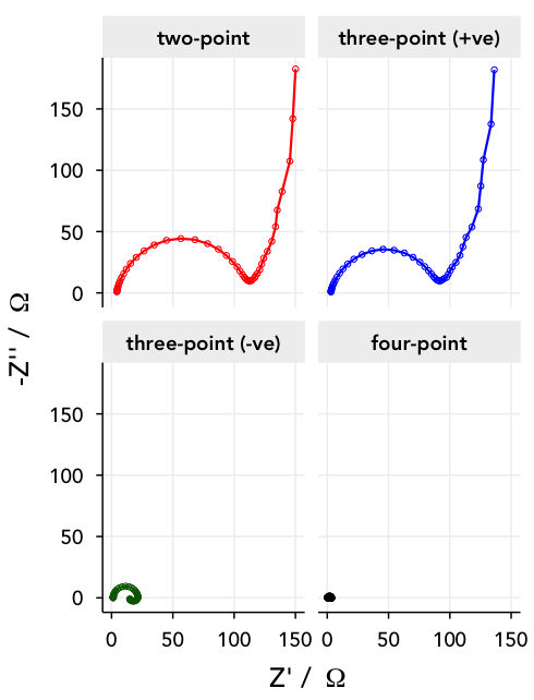
Note: lithium metal is, unfortunately, not a very stable or well-behaved electrode, and shows some difficult-to-model behaviour towards lower frequencies.