RC circuits
Now that we’ve introduced some of the maths behind impedance, and the plots we use to represent it, we can start to look at the mathematical definitions and the impedance response of two of the most basic electrical circuit components – resistors and capacitors – and combinations of them.
Impedance of a resistor
This is the simplest electrical circuit, and the easiest to understand. Resistors, as you surely know, obey Ohm’s law, so the current is always proportional to the voltage, there is no reactive part (i.e., phase shift) and so no dependence on frequency whatsoever. We can just write that down like this:
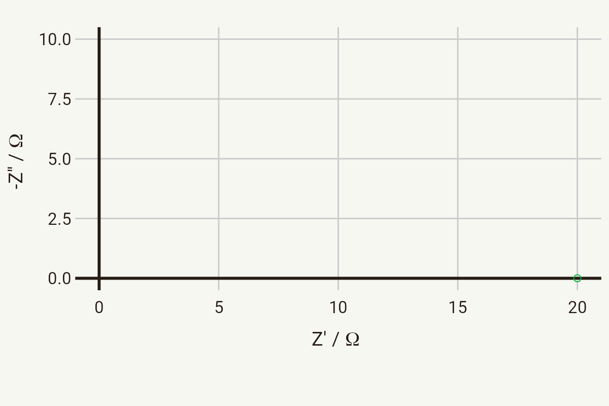
where R is the resistance. The Nyquist plot for a resistor then is very simple – it’s just a single point on the x-axis at any frequency. The below plot shows the Nyquist plot for a resistor with a resistance of 20 Ω.
Impedance of a capacitor
Capacitors have a purely reactive impedance. An ideal capacitor has zero resistance. When an alternating voltage is applied across a capacitor, the current leads the voltage (the phase is -90°), and the impedance is inversely proportional to the frequency. That is, the impedance increases with decreasing frequency. Consider applying a DC voltage across a capacitor – after a long enough time, the capacitor is fully charged and no more current flows. The impedance is effectively infinity. The equation describing a capacitor is:
where
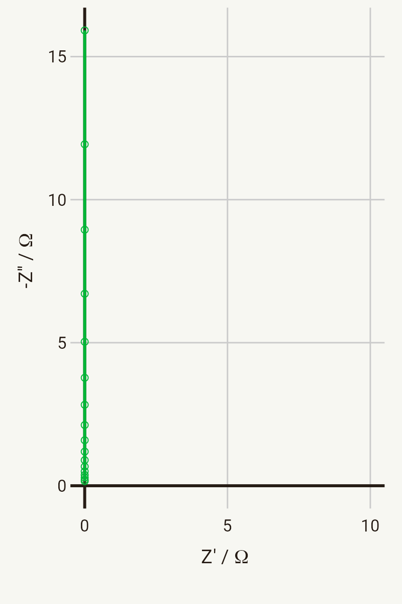
he Nyquist plot for a capacitor therefore looks like a vertical line, where Z’ = 0 for all frequencies. The below plot shows the Nyquist plot for a capacitor with a capacitance of 1 mF, in the frequency range 1 kHz – 10 Hz. The highest frequency points have the lowest impedance, with the impedance increasing as frequency decreases.
Capacitances arise all over the place in electrochemical systems, pretty much anywhere you have an interface – most often from the capacitance of the double layer, but also dielectric capacitance, or at grain boundaries in solids, and so on.
This is all fairly straightforward so far, so now we’re going to consider combining some of these different circuits together.
RC circuits
Series RC circuit
In series, the impedances are additive:
The impedance of the series RC circuit is therefore just the addition of the individual impedances of the resistor and the capacitor together:
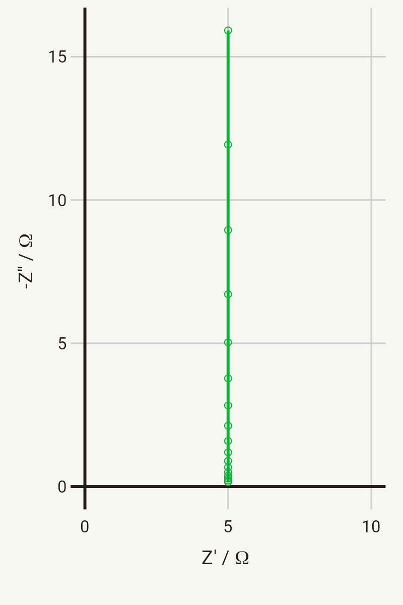
The Nyquist plot for a series RC circuit (where R = 5 Ω, C = 1 mF, in the frequency range 1 kHz – 10 Hz) is shown below. As you might expect, the real impedance Z’ is equal to the resistance of the resistor for all frequencies, and the imaginary part of the impedance follows the same behaviour as for the ideal capacitor.
You can consider the series RC circuit as a simple model for things like a blocking interface – for example an inert electrode immersed in a conducting electrolyte – where R represents the ionic resistance of the electrolyte, and C represents the capacitance of the double layer on the electrode surface.
This also represents two electrodes in an electrolyte (i.e., a complete cell), because a series circuit with two capacitors (i.e., C-R-C) simplifies down to a single RC unit anyway, if you follow the equations above.
Parallel RC circuit
Now, let’s consider the parallel case.
In parallel, the admittances (i.e., the reciprocals of the impedances) are additive:
So then we can write the expression for the parallel RC circuit like so:
If we rearrange that equation for
From this equation you can see that at high frequency, i.e.,
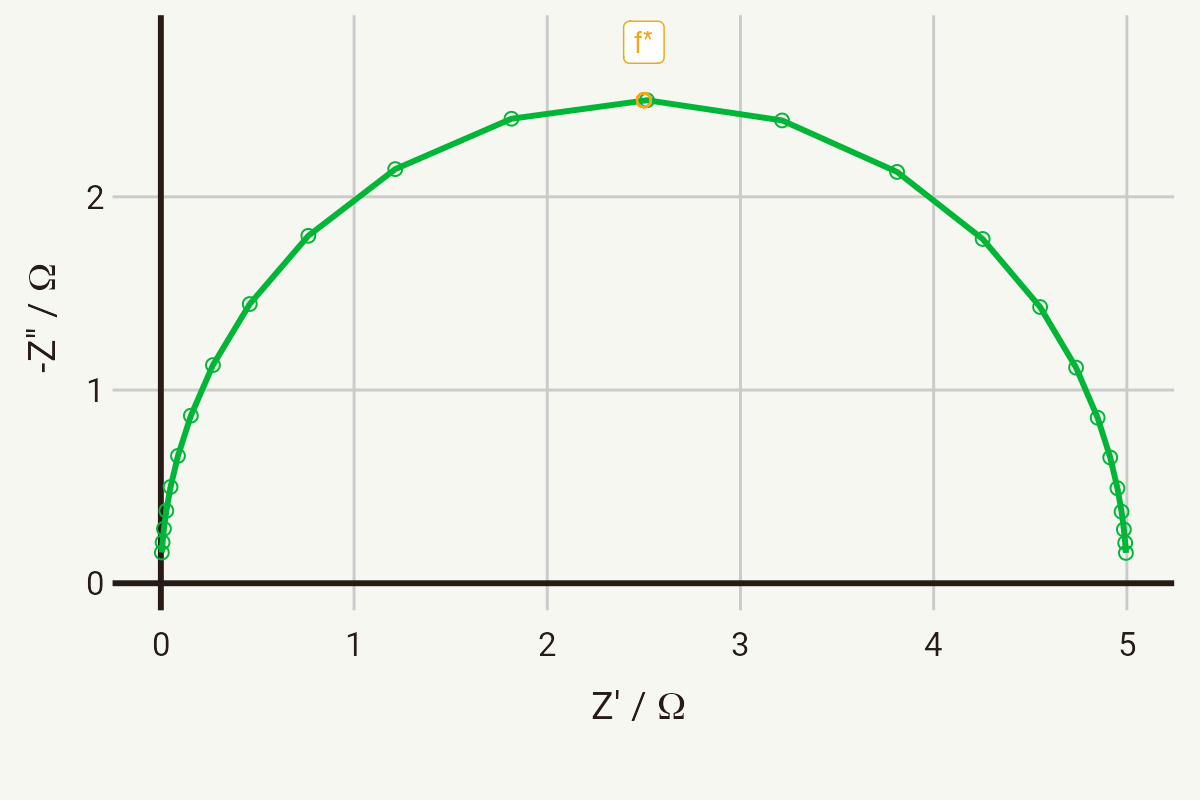
Semicircles in the Nyquist plot are very common in electrochemical impedance, and are usually associated with processes such as charge transfer, because at an electrode surface the transfer of charge happens in parallel with the charging of the double layer capacitance – hence the semicircle.
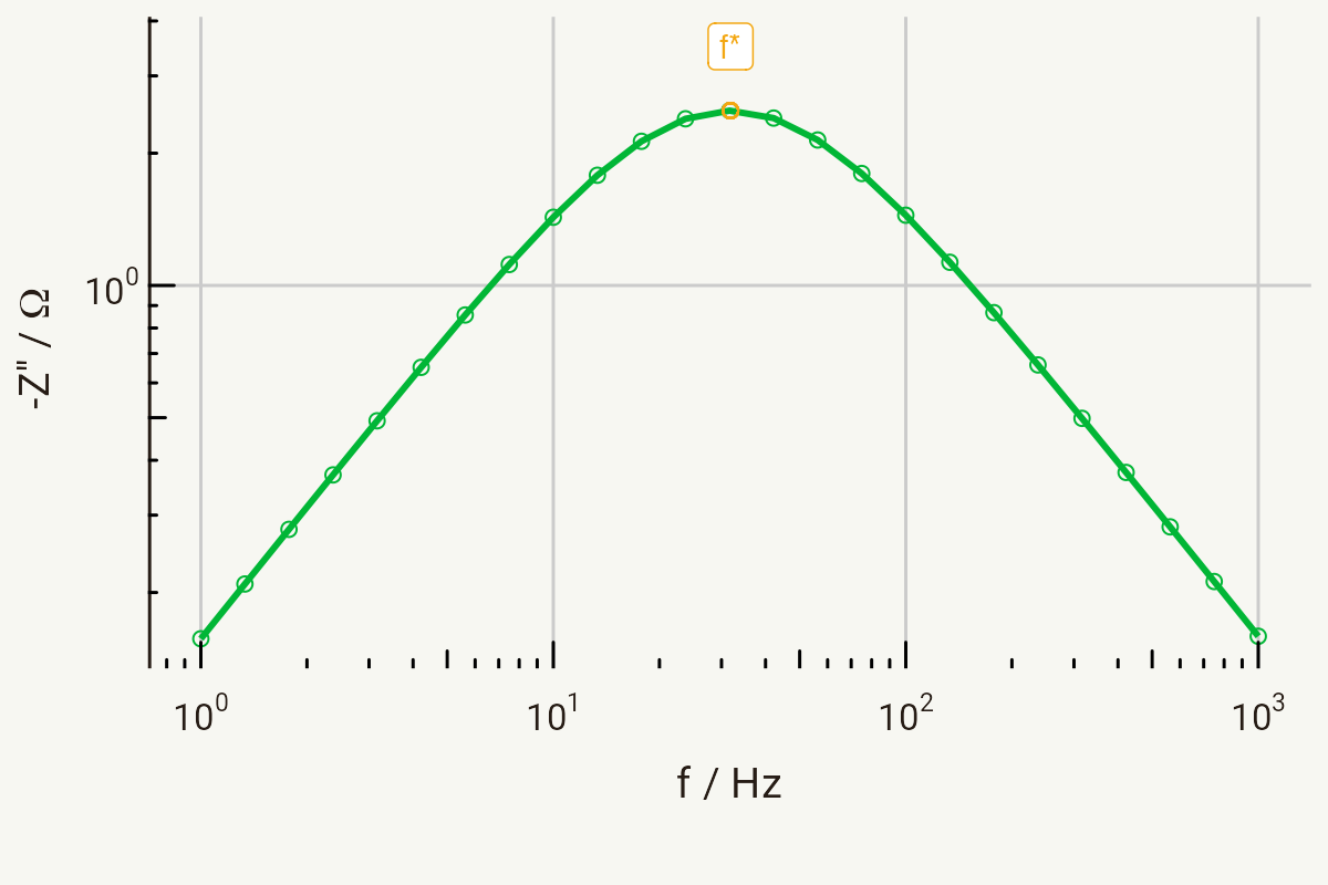
You’ll also note that I’ve marked the very top of the semicircle with f*. This is known as the relaxation frequency, and relates to the RC time constant of the circuit. From the previous equation, you will see that the peak of the semicircle occurs when
This is an important concept in EIS, because it tells us something about the timescales on which different processes are occurring. This equation also allows you to calculate capacitances in these elements knowing only the resistance (from the diameter) and the relaxation frequency.
This is where the Bode plot comes in handy. The top of the semicircle simply appears as a peak in a plot of the imaginary part against the frequency, with log scaling:
Since I simulated the circuit with values of R = 5 Ω and C = 1 mF, you should be able to follow that:
and see on the Bode plot above that the peak is at around 32 Hz.
Another reason this is important is that the time constant (that is, the frequency dependence) of these elements of course affects the order in which they appear in the Nyquist plot. Elements with a smaller time constant (i.e., a higher relaxation frequency) will, naturally, appear at higher frequencies in the impedance spectrum. Of greater concern, however, is that elements with very similar or the same time constants will tend to overlap. I’ve included a Shiny app for simulating a circuit made up of two parallel RC units in series to show this. Have a go at changing the parameters, and see how they affect what the Nyquist plot looks like.

