Diffusion Impedance
Mass transport processes, such as diffusion, migration and convection, are a key aspect of electrochemical systems. In this subsection, we will look at fundamental models for the effect of diffusion processes on impedance. As with the CPE, we invent some new circuit elements to describe these, but these can be approximated using the familiar resistors and capacitors, as we will see.
Semi-infinite diffusion
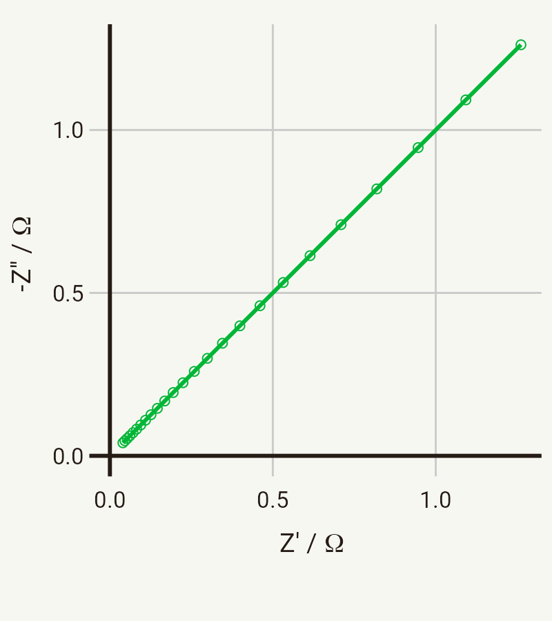
The simplest and most common circuit element for modelling diffusion behaviour is the Warburg impedance or Warburg element, which models semi-infinite linear diffusion – that is, diffusion in one dimension which is only bounded by a large planar electrode on one side.
The equation for this element is relatively simple:
where
And if you’re looking at this thinking that this line look very much like a constant phase element but with a phase angle of 45°, then you’d be right – mathematically they are very much the same. In fact, some popular impedance analysis softwares do not actually provide a semi-infinite Warburg element, so a convenient alternative for this is a CPE element with n fixed at 0.5. This gives slightly different numbers back when fitting – if you use a CPE, you will get back the Q0 value, rather than the Warburg coefficient
But what does
then
here, in addition to the usual constants,
The transmission line
Conventional “Fickian” diffusion is not the only process which gives rise to this type of impedance in electrochemical systems. In batteries, the porosity of electrodes also gives rise to a similarly characteristic 45° line in the Nyquist plot.
This was described in detail by de Levie, who proposed the transmission line model for an electrode with cylindrical pores filled with electrolyte:
Consider the two parallel “rails” as being the electronic resistance in the electrode material itself and the ionic resistance in the electrolyte respectively. The capacitors represent the double layer capacitance.
This equivalent circuit, when infinitely long, gives an impedance response which is identical to the Warburg impedance above. Practically, however, porous electrodes have a finite length, and so show a 45° line only in a certain frequency range. The impedance response due to finite diffusion is discussed below.
A final point on the transmission line: if the transmission line shows the same response as Fickian diffusion, can the case of a porous electrode be considered diffusion as well? In a sense, yes. The movement of ions through the pores is coupled to the movement of electrons through the pore walls. This is an example of ambipolar diffusion.
Finite diffusion
Often in the “classic” electrochemical setups, diffusion often appears semi-infinite because the timescale of the experiment is not long enough for the system to reach a steady state. However, in many real systems and in some standard experiments, diffusion is either naturally, or by design, limited. This gives rise to finite diffusion behaviour, which shows a different response than the standard Warburg impedance.
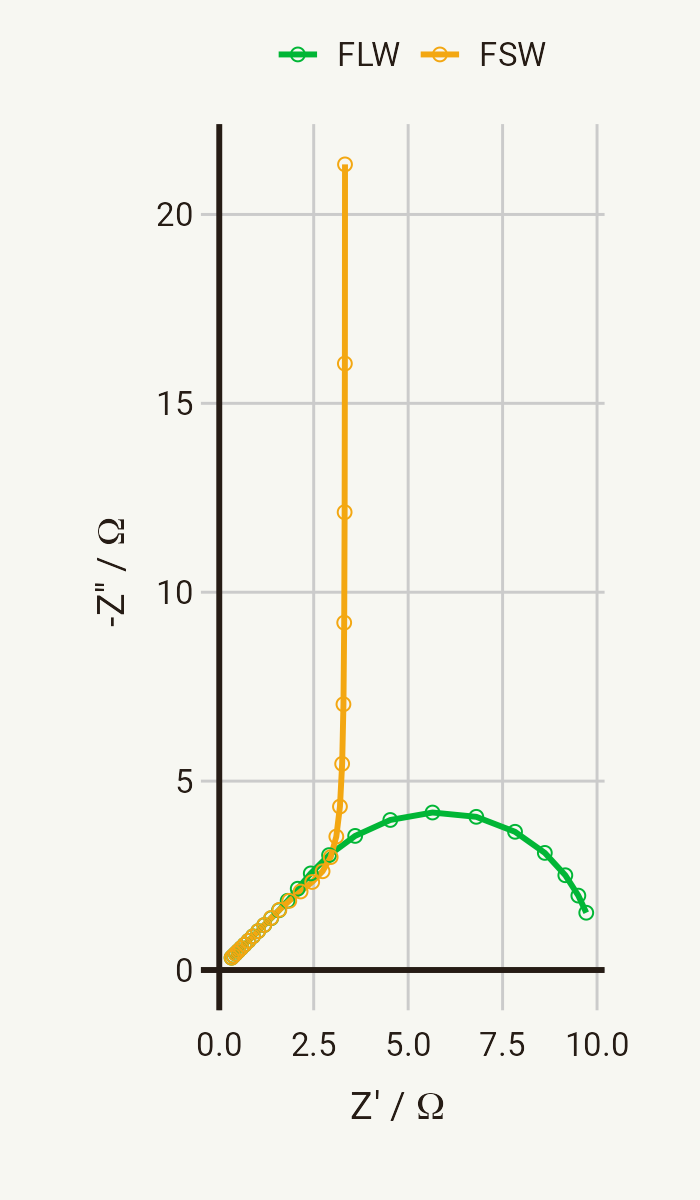
There are two important equivalent circuit elements for finite diffusion. They are the finite length Warburg (FLW) and the finite space Warburg (FSW), sometimes called the “short” and “open” Warburg elements respectively. Their responses in a Nyquist plot look like this, with parameters Z0 = 10 Ω and
Let’s look at the FLW first. Mathematically, it can be written as:
The two parameters
This response is typically associated with diffusion (or more generally mass transport) through a layer with a finite length. A classic example of this is the response of the rotating disk electrode - the point of which being to reduce the distance from the electrode to the bulk by controlling convection, rather than diffusion in this case.
The FSW has a rather similar definition:
In this case, the response tends towards capacitive-like behaviour at low frequencies, where
You can find a number of different definitions of these finite elements and it’s easy to get confused. One source of confusion can be from defining these elements in terms of admittance. For example, the FLW is frequently defined like this:
You might have noticed that this definition contains


