Constant Phase Elements
So far, we’ve looked at the impedance response for some ideal resistors and capacitors and some simple combinations of them. Unfortunately, in electrochemical systems we often encounter processes which don’t have a “real” equivalent electrical component, so we have to invent some. One of the most common such elements is the constant phase element, or CPE.
One of the most common circuit elements for modelling non-ideal behaviour is the constant phase element (CPE, or sometimes Q). This is a common symbol for this circuit element:
You might think that it looks like a wonky capacitor – and you’d be right, because this circuit element exists largely to describe capacitance as it appears in real electrochemical systems, because of things like rough surfaces, or a distribution of reaction rates. It is an imperfect capacitance – the effective capacitance and ‘real’ resistance are increasing as the frequency decreases. The origins of CPE behaviour are numerous and some of them quite complex, but there are good guides explaining this elsewhere.
The mathematical definition is very similar to that of the capacitor as well:
where n is the constant phase,
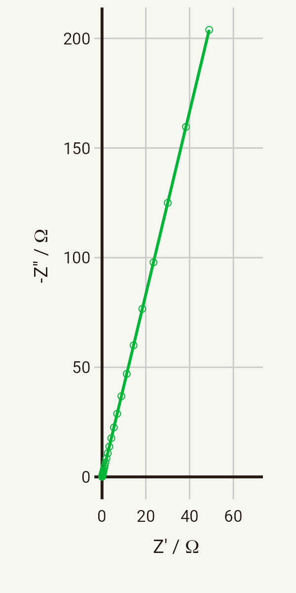
So, what does the Nyquist plot look like? You might have guessed by now that the Nyquist plot for a CPE looks similar to a capacitor – a straight line, but with a phase of
R-CPE or RQ circuits
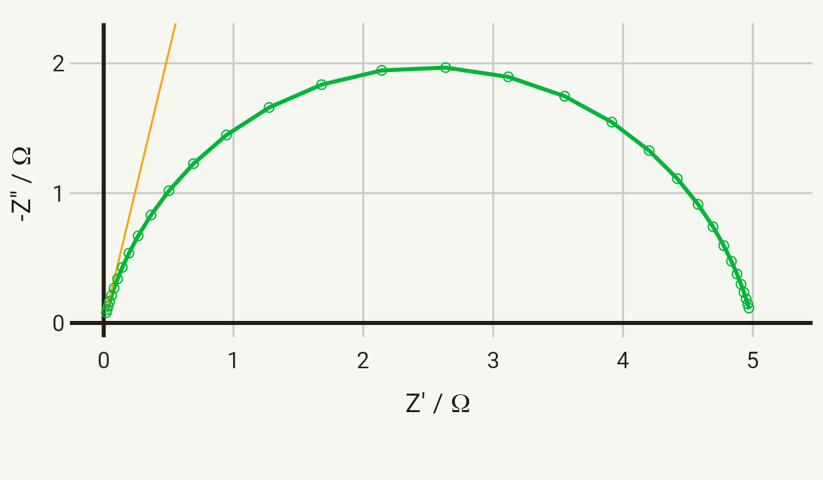
It should be fairly clear by now what the Nyquist plot of a series R-CPE element looks like, so I’ll only show the parallel case, the characteristic “depressed” semicircle. The below plot shows the Nyquist plot for a CPE with a Q of 1 mS sn, where n = 0.85, in parallel with a 5 Ω resistor, in the frequency range 10 kHz - 10 Hz.
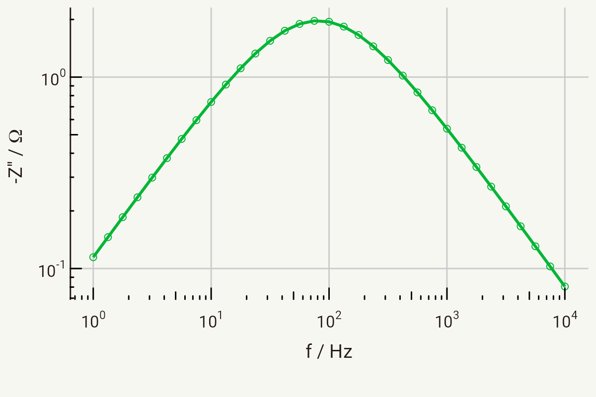
The Bode plot for a parallel R-CPE circuit looks very similar to that of a parallel RC circuit, but with a subtle difference: on a log-log plot (i.e., log(-Z’’) vs log f), the gradient of the straight line gives you the n value:
You may be able to see from the above plot that in the high frequency region (to the right of the peak) the gradient is -0.85, and in the low frequency region (to the left of the peak) the gradient is +0.85. Being able to estimate these values from Bode plots can be a useful technique to estimate parameters when performing equivalent circuit fitting, as we will see later on in this section.
Can I calculate the real capacitance?
Q0, according to the mathematical definition of the CPE, has units of S sn (that’s siemens-seconds-to-the-power-n), which have no real physical meaning. However, it is possible to determine the actual capacitance behind the CPE when you have a parallel R-CPE circuit. Think about the units again – you should be able to see that:
Rearranging this equation gives:
This equation holds as long as the phase angle does not deviate too far from -90° (n > 0.75). I won’t go into this further, though – the ConsultRSR webpages on EIS provide some useful reading on this point.


